Article Text

Abstract
Introduction Body armour typically comprises a fabric garment covering the torso combined with hard armour (ceramic/composite). Some users wear only soft armour which provides protection from sharp weapons and pistol ammunition. It is usually recommended that body armour is worn against the body with no air-gaps being present between the wearer and the armour. However, air-gaps can occur in certain situations such as females around the breasts, in badly fitting armour and where manufacturers have incorporated an air-gap claiming improvements in thermophysiological burden. The effect of an air-gap on the ballistic protection and the back face signature (BFS) as a result of a non-perforating ballistic impact was determined.
Methods Armour panels representative of typical police armour (400x400 mm) were mounted on calibrated Roma Plastilina No 1 and impacted with 9 mm Luger FMJ (9×19 mm; full metal jacket; Dynamit Nobel DM11A1B2) ammunition at 365±10 m/s with a range of air-gaps (0–15 mm). Whether or not the ammunition perforated the armour was noted, the BFS was measured and the incidence of pencilling (a severe, deep and narrow BFS) was identified.
Results For 0° impacts, a critical air-gap size of 10 mm is detrimental to armour performance for the armour/ammunition combination assessed in this work. Specifically, the incidences of pencilling were more common with a 10 mm air-gap and resulted in BFS depth:volume ratios ≥1.0. For impacts at 30° the armour was susceptible to perforation irrespective of air-gap.
Conclusions This work suggested that an air-gap behind police body armour might result in an increased likelihood of injury. It is recommended that body armour is worn with no air-gap underneath.
- penciling
- perforation
- bullet deformation
- BFS
- BABT
Statistics from Altmetric.com
Key messages
Body armour with air-gaps underneath has reduced performance.
Air-gaps under body armour may lead to an increase in pencilling behind armour blunt trauma (BABT) injuries.
Angled shots are more likely to perforate body armour.
Introduction
Many organisations and manufacturers recommend that body armour is worn close to the body, but this is not always possible. For example, body armours worn by some female police personnel often result in an air-gap between, above and underneath the breasts. Poorly fitting body armour and the wearing of items such as a personal mobile phone under a body armour may also result in air-gaps between the body and the armour.
Some body armour manufacturers produce armour which incorporates spacer fabrics on the inner surface with the claim that microclimate control is enhanced. Whether such designs actually reduce thermal burden via microclimate cooling is not known; although it is recognised that air-gaps between clothing and the body can both negatively and positively affect thermophysiological loading.1 2 It is not known if such air-gaps affect the protective performance of the body armour.
A non-perforating ballistic impact on to body armour may result in a behind armour blunt trauma (BABT) injury; these are typically contusions and fractured ribs3 which occur because the armour is deformed transversely during the impact event.3 During ballistic testing, body armour is usually strapped flat against a backing clay material such as Roma Plastilina No 1 to measure the back face signature (BFS) due to a non-perforating impact event, but this is not always comparable to how the armour is worn. The maximum allowable BFS measurement for UK police armours is 44 mm.4 Pencilling is a specific type of BFS described in test standards which is also known as narrow indentation BFS… “This is the general term for a narrow diameter indentation in the Roma Plastilina backing material caused by the bullet. The armour has not been perforated but the material has failed to stop the round from causing a deep narrow indentation, which has the potential to cause a serious or fatal injury.”4 5 There is no correlation between the BFS and a specific BABT injury.3 4
Previous comment on air-gaps behind personal armour is sparse. References to ‘bunching’ and ‘puffing’ (thus creating an air-gap) of soft body armour were made by Miner in 1990 as a comment on the effectiveness of the armour test standards of the day.6 These mechanisms were claimed due to the use of strapping across the armour panels and led to a high rate of non-reproducible perforating failures in the armour. That armours might be worn ‘loose or close to the body’ has been noted with observation that some armours only perform if worn close to the body.7 However, no data or source materials were provided to corroborate the statements made in either article.
The aim of the work described in this paper was to determine the effect of a 0 mm, 5 mm, 10 mm and 15 mm air-gap on the performance of a typical soft-body armour system; two impact angles were considered (0°, 30°).
Methods
Panels (400 x 400 mm) of HG1/A+KR1 body armouri were mounted on calibrated Roma Plastilina No 1.4 Such armour is representative of that used in modern police body armour. The panels were impacted using 9 mm Luger FMJ (9×19 mm; full metal jacket; Dynamit Nobel DM11A1B2) rounds at 365±10 m/s using a #3 proof housing fitted with 9 mm calibre barrel.4 Each body armour panel was impacted in 10 locations (Figure 1).4 Impact velocities were measured using a Doppler radar.

Shot pattern.
Two impact angles (0° and 30°) were used; the angle was a ‘right shoulder back’ position (sometimes referred to as the Weaver Stance) designed to simulate a front impact on a body armour panel being used by right-handed personnel in a firing position.
Air-gaps of 5 mm, 10 mm and 15 mm were created using a plywood picture frame of the appropriate thickness mounted between the body armour panel and the Plastilina (Figure 2). To prevent sagging of the body armour panel and maintain the air-gap, a small piece of self-adhesive foam was placed in the centre of the armour panel at a minimum distance of 50 mm from any shot location. The body armour panel and picture frame (when used) were strapped to the Plastilina block using Velcro strapping.
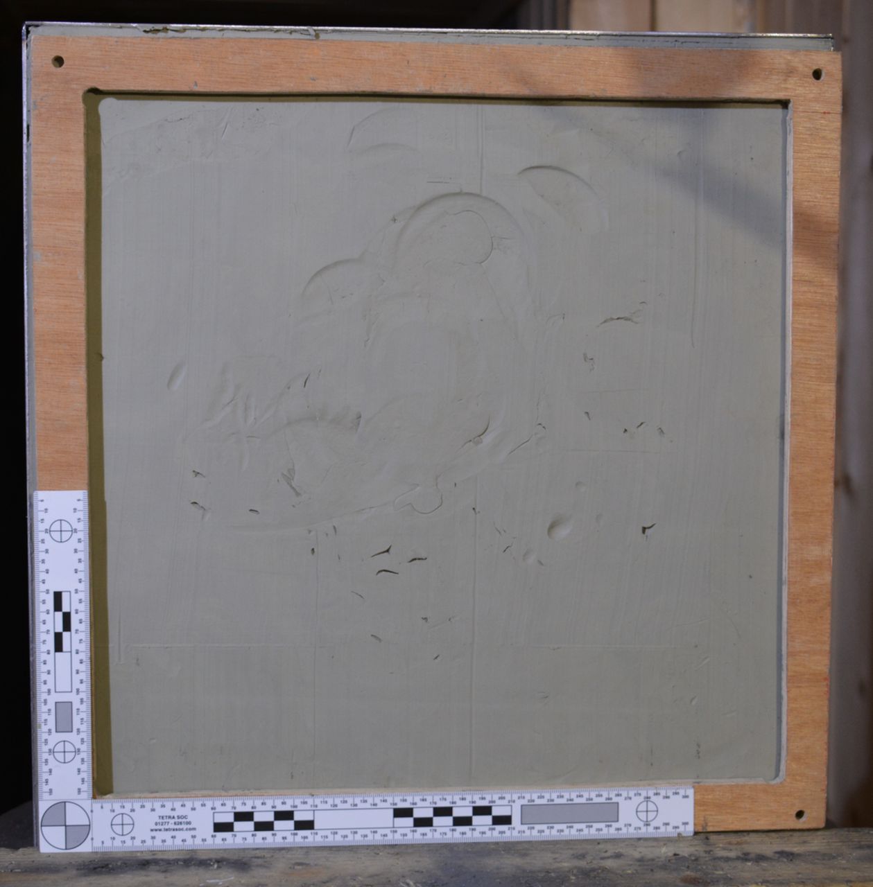
Creation of air-gap; plywood picture frame on calibrated Plastilina block.
Data for each combination of impact angle and air-gap were collected (n=10); whether or not the shots perforated the specimen was noted after each shot. The BFS in the Plastilina due to each non-perforating impact was measured (to the nearest mm) using calibrated depth measuring callipers.4
After 10 shots on each armour pack, Plaster of Paris was used to fill the BFSs in the Plastilina block located behind the armour pack. After solidification, the BFS moulds were stored in resealable polymeric bags to maintain water homoeostasis. The mass (gram), volume (cubic centimetre) and base surface area (square centimetres) of the BFS moulds were determined. BFS mould mass was measured using calibrated Mettler Toledo PB153 scales. The volume of the BFS mould was calculated by comparing the mass of each BFS mould to that of a standard 250 cm3 of dried plaster. The density of the standard mould was calculated from the volume of the container used and the mass of the subsequent dried moulding and was calculated to be 1.33 g/cm3. The surface area of each BFS mould was calculated by tracing the base of the mould onto card; this area of card was then weighed. A piece of the same card of known area (2500 mm2) was then used to calibrate the measurements by considering the ratios of mass and area.
Mean, SD and coefficient of variation data were calculated when applicable. Differences in data due to the magnitude of the air-gap were determined using analysis of variance (ANOVA) and Bonferroni post hoc tests (IBM SPSS Statistics 22.0).
Results
Effect of air-gap on armour performance
Data (BFS; non-perforation and perforation) are presented in Table 1; the two impact angles are presented separately.
Back face signature (BFS) data (n=10 shots for each impact angle and air-gap combination)
For 0° impacts, no perforations occurred for a 0 mm air-gap; at each of the other air-gaps tested one perforation occurred (Table 1; Figure 3A). The mean BFS was greatest at a 10 mm stand-off (41 mm) with the other air-gaps of 0 mm, 5 mm and 15 mm resulting in mean BFSs of 34 mm, 35 mm and 33 mm, respectively (Table 1). Smaller air gaps resulted in less variation in BFS compared with larger air-gaps (0 mm CV=8.24%, 5 mm CV=6.93%, 10 mm CV=14.38% and 15 mm CV=17.78%). ANOVA indicated that air-gap size significantly affected BFS (F3,31=4.68, p≤0.01). A Bonferroni post hoc test concluded that there was no statistically significant difference in BFS due to air-gaps of 0 mm, 5 mm and 15 mm. However, for an air-gap of 10 mm, there was a statistically significant difference compared with air-gaps of 0 mm (t16=2.99, p≤0.05), 5 mm (t16=2.41, p≤0.05) and 15 mm (t15=3.40, p≤0.01).

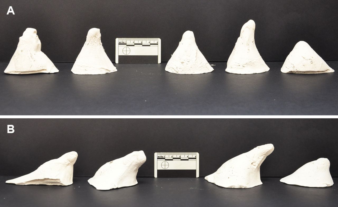
Typical moulds of back face signature (BFS) from (A) 0° impacts (left to right—first four are pencilling impacts, fifth is a non-pencilled impact), (B) 30° impacts (left to right—first three are pencilling impacts, fourth is a non-pencilled impact).
For 30° impacts, 40%–50% of shots perforated the armour irrespective of air-gap size (including 0 mm) (Table 1; Figure 3B). The mean BFS was greatest for a 10 mm air-gap (36 mm); all of the other air-gaps resulted in a mean BFS of 31 mm. Variation in the mean BFS data was lower with no air-gap (CV=19.01%) compared with specimens with air-gaps (5 mm CV=29.21%, 10 mm CV=26.23% and 15 mm CV=24.70%). Analysis of variation concluded that there was no significant difference in BFS due to the presence of an air-gap for 30° impacts (F3,17=0.48, p=NS).
Effect of shot location on BFS
Due to the high failure rate (perforations plus BFS >44 mm) witnessed at the 30° impact angle, the effect of shot location on BFS data was considered for only the 0° impact angle data. The shot locations were grouped as following; shots 1, 3, 5 and 7 were considered corner shots; shots 2, 6, 8 and 9 were considered edge shots; shots 4 and 10 were considered centre shots (Figure 1). There was a statistically significant difference in BFS among shot locations due to the 10 mm and 15 mm air-gaps (F6,23=3.51, p≤0.05). Bonferroni post hoc tests for the 10 mm air-gap data concluded that there was a statistically significant difference between edge-shots and corner-shots (t6=2.59, p≤0.05) and edge-shots and centred-shots (t6=3.26, p≤0.05). Bonferroni post hoc tests for the 15 mm air-gap data concluded that there was a statistically significant difference between corner-shots and centred-shots (t5=2.99, p≤0.05) and edge-shots and centred-shots (t5=2.89, p≤0.05).
A new determinant for identifying pencilling
A 10 mm air-gap combined with 0° impacts produced the greatest proportion of pencilling signatures under the armour. Only one BFS failure did not correspond to a pencilling deformation. A new numerical determinant of the presence of pencilling was produced using the depth:volume ratio. A ratio of depth:volume equal to or greater than 1 correlated to the presence of a pencilling style of deformation in the armour (0° pencilling shot data Table 2). Non-pencilling BFS depth:volume ratios varied from 0.70 to 0.99.
Back face signature (BFS) depth:volume data for 0° pencilling shots
Discussion
There are three matters that require discussion: the effect of air-gap on BFS, the effect of bullet impact position on armour performance and definition of pencilling.
The effect of air-gaps on BFS does not appear to have been reported in the peer reviewed literature previously. The data presented in this work suggested a critical air-gap (10 mm) may exist which results in degradation of armour performance (including an increase in the propensity of pencilling) for the armour/ammunition combination considered. The frequency of armour perforation increased for a 30° impact angle; similar observations have been previously made for angled shots impacting soft armour.8
The effect of a non-perforating impact on an armour pack appears to vary according to position when an air-gap of either 10 mm or 15 mm was present. This may have implications for standard test method design.
Manufacturers, test houses and users often request a numerical definition for pencilling. The UK Home Office define pencilling as… “Where the bullet has forced the armour sample into the backing material causing a narrow indentation—the depth of the indentation shall be no more than 20 mm for all threat levels on all sample sizes’’.4 However, this does not define the 'narrowness' of the indentation. By considering the depth and volume of the BFS as in this work a numerical determinate of pencilling has been proposed. However, this needs to be assessed using different armours and different threats.
Conclusions
This work suggested that an air-gap behind soft body armour representative of that used by current police forces might result in an increased likelihood of injury. It is recommended that soft-armour is worn with no air-gap underneath. For 0° impacts, a critical air-gap size of 10 mm appears to exist for the armour/ammunition combination assessed in this work. Specifically, the incidences of pencilling were more common with a 10 mm air-gap. This may be related to a change in bullet/armour/backing interaction and bullet deformation. Variability in BFS increased with air-gap magnitude. The BFS was affected by shot location for air-gaps of 10 mm and 15 mm. We have proposed a new determinant for pencilling in 0° impacts as a BFS depth:volume ratio≥1.0; however, this needs to be further investigated using different armours and projectiles. For impacts at 30° the armour was susceptible to perforation irrespective of air-gap.
Acknowledgments
The authors acknowledge the support of Home Office Centre for Applied Science and Technology (CAST). This paper is written from the MSc thesis (Forensic Ballistics) of the author LT which can be obtained from Cranfield University, UK. The authors also acknowledge Home Office CAST for providing the armour and the ammunition used.
Footnotes
↵ i The body armour panels were all from the same manufacturer and provide resistance to perforation from low-velocity pistol ammunition and knives. They were supplied by a manufacturer approved by The Home Office. The manufacturer and the materials used in the armour cannot be released at the request of The Home Office. These armours can be covert or overt in their use.
Contributors CM suggested this study which was completed by LT for his MSc thesis in Forensic Ballistics with assistance from DJC and CL. DJC wrote this paper from LT’s thesis. All other authors approved the manuscript.
Competing interests None declared.
Provenance and peer review Not commissioned; externally peer reviewed.
Data sharing statement The original data is in the MSc thesis of the author LT which can be obtained from DJC.